Logic Gates
- Performs a basic operation on electrical signals
- Accepts one or more inputs and produces a single output signal
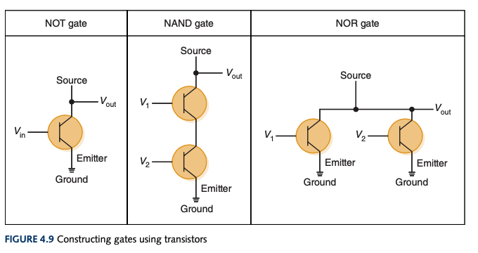
- Easiest gates to make are
NOT, NAND, and NOR gates
NOT
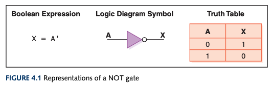
- Accepts an input
- Output is inverted of input
- An inverter
- Boolean algebra:
A'- The mark comes after a value being negated
- Sometimes shown as horizontal bar over value being negated
- Logic diagram:
NOT Truth Table
AND
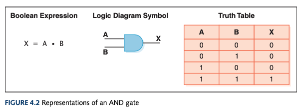
- Accepts two inputs
- Outputs
1 if both inputs are 1
- Outputs
0 if either input is 0
- Boolean algebra:
A • B or A * B or AB or A ^ B
AND Truth Table
OR
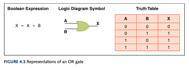
- Accepts two inputs
- Outputs
0 if both inputs are 0
- Outputs
1 otherwise
- Boolean algebra:
OR Truth Table
XOR
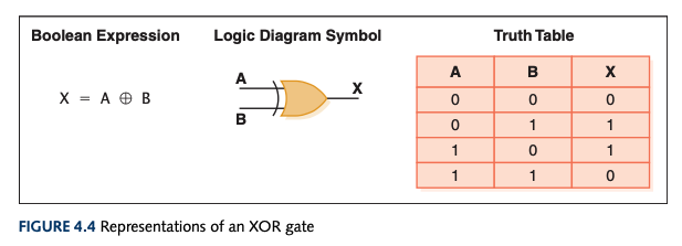
- Exclusive
OR
- Only differs from an
OR if both inputs are 1
- "When I say or, I mean one or the other, not both."
- Accepts two inputs
- Outputs
0 if the two inputs are the same
- Outputs
1 otherwise
- Boolean algebra:
XOR Truth Table
NAND
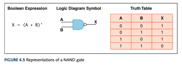
NOT + AND
- It's an
AND gate that gets inverted
- Accepts two inputs
- Outputs
0 if both are 1
- Outputs
1 otherwise
- Boolean algebra:
NAND Truth Table
NOR

NOT + OR
- It's an
OR gate that gets inverted
- Accepts two inputs
- Outputs
1 if both input is 0
- Outputs
0 otherwise
- Boolean algebra:
NOR Truth Table
Computer Science